
« $toneßroke Manor »
The KGØZP Super Linear-Loaded Inverted V
How do you fit a full length 160 meter antenna into a 40 foot deep yard?
Install the KGØZP Super Linear-Loaded Inverted V, of course!
The KGØZP Super Linear-Loaded Inverted V allows you to select your two favorite and most used frequencies as band centers, and offers excellent bandwidth as well.
The designers installation centerpoints are set at 1.840 the center of the DX window or calling frequency and 1.875 at an SWR of 1.1-1
The bandspread at 1.5-1 is 20 kc at each center or 40 kc to an SWR of 2-1
The linear-loading section is mounted near enough to the ground that you can easily install or remove precut pigtails using an alligator clip to move the center point temporarily to make that sked, or you can tune the whole 160 meter band with a simple antenna tuner.
The formula for construction is the same as for any dipole 468/fMhz and the design will work equally well on 80 or 40 meters.
Reader Please Note: The photos on this page are greatly compressed to insure quick downloading.
The link accompaning each photo will cause the uncompressed full size photo to download.
It would be impossible to show an overall view of the whole antenna system in such a way that you could see the wires.
With that in mind, I have taken a couple of daylight pictures as well as flash night pictures which allowed me to highlight the wires against a black sky.
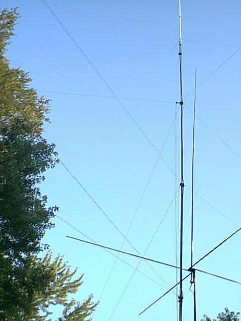
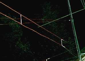
Lets take a thumbnail look at a daylight view of the Rohn 50 foot push-up pole utilized for this installation. This is quite a busy photograph, so I will name the items in descending order to help pinpoint the areas relevant to the KGØZP Super Linear-Loaded Inverted V. Link to view photo in hi-res!
The white stick at the top extending off the upper edge of the photo is a Diamond Tri-bander, model X3200A, fed with 9913 coax.
Directly below the tribander is the first guying ring. This is a dummy ring and is used to ground and hold the upper wire of a Wermager type Broadband Sloper. In the full sized photo you can just barely see this wire extending left forward.
The highest of the three actual guying rings (second one down from the top) is at the 40 foot high point on the tower, a pulley is connected to this guying ring and through it is threaded a high quality flagpole rope. This rope can be used to raise and lower the balun for experimenting with different antenna designs, without changing the position of the push-pole.
The KGØZP Super Linear-Loaded Inverted V, the topic of discussion, is connected to this balun. The tension on the wires is so great that it holds the balun outward, the line descending from the bottom of the balun is Super Mini-8 coax. The pull of the Inverted V's two antenna wires is offset by two guy wires on the other side of the guying ring. I have a wide yard and could keep the apex slightly wider than 90 degrees.
The next guy ring down is at the 30 foot height point and has nothing more than three guy wires connected to it.
The lowest guy ring visible in the photograph is at the 20 foot level, and is the feedpoint for the Fan portion of a Wermager type Broadband Sloper originally used on 160 but now cut for 80 meters. I would like to mention again that the upper wire of the Wermager type Broadband Sloper is the wire grounded to the push-pole at the dummy guy ring at the very top. The other end of this wire is tied to the same location as the guy wire coming from the 30 foot guy ring, which places the metal guy wire directly between the driven Fan and the grounded sloper element of the Wermager type Broadband Dipole.
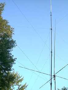
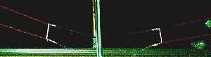
 This photo is a view showing the East outbound leg of the Super Linear-Loaded Inverted V. In the upper left of the photo, you can see the single sloping wire descending from the balun. The two horizontal wires below comprise part of the Linear-Loading section. Link to view photo in hi-res!
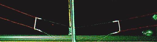
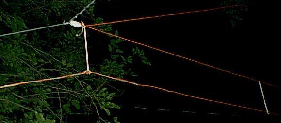
The remaining photo's were taken at night using a flash, then enhanced to make the wires more prominent.
In this first photo, you can easily see that the Linear-Loading section is a good distance away from the push-pole. I used a distance of 5 feet in this installation, but you can reduce this distance to 3 feet if necessary. The vertical spacers are drinking straws, one nested inside the other for greater strength, a nylon tie line is fed through the center of the straws. Link to view photo in hi-res!
The upper tie off lines are located 1 foot above the standoff mounted to the eave. The lower tie off lines should also be located at or just above the standoff. Original twine used during initial setup is still visible and should have been removed before taking the photo.
The white insulator some 5 feet above the linear loading section is the feedpoint for the Fan portion of the Wermager type Broadband Sloper.
SPECIAL NOTATION:
The upper wire and the lower wire of the linear-loading section are connected at this end only. This will be described in greater detail in the construction notes section. Link to view photo in hi-res!
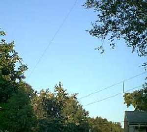
These last two photos show the East and West outbound ends of the KGØZP Super Linear-Loaded Inverted V.
If you look closely, you can see the pigtails wrapped around the lower nylon guys.

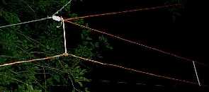
In the photo on the left of the East outbound end, the wire from the balun down to the insulator is not visible. The upper guy wire from the insulator is metal, the lower is nylon. An additional twisted wire above the insulator is used to lift the linear loading section slightly higher than the existing guy mount allows, I did this only because I had something above each outbound end to tie to. Link to view left photo in hi-res!
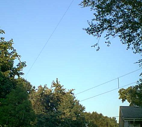
The right photo shows slightly greater detail and the antenna wire from the balun is clearly visible. There are no electrical connections at the outbound end of the linear-loading section. Link to view right photo in hi-res!
Again, if you look closely, you can see the pigtail extension wrapped around the lower nylon guy.
Construction Notes:
The construction of the Super Linear-Loaded Inverted V is quite simple and follows the same formula as for a standard dipole. 468/fMhz (FourHundredSixtyEight divided by the Frequency in Megahertz give you the total length in feet for a 1/2 wave dipole). In practice you will use two wires, each being 130 feet long. The antenna shown in the photos is made from 14 guage insulated copper wire. I ran out of insulators and am temporarily using loops made from 1/4 inch nylon cord at the push-pole end of the linear-loading section. If you start with two 130 foot long wires, you do not have to measure the turning or ending points, they will fall in place depending upon the height you install the horizontal portion of the antenna.
The height of the feedpoint can vary considerably, however, the higher the better. If you can only go up 30 or 35 feet, the antenna will still perform almost as well, but you will require a further horizontal distance to work in. With the feedpoint at 40 feet, the sloping elements are roughly 60 feet long at 40 feet away from the push-up pole. Any distance from 40 feet to 80 feet in length seems to make little difference in the performance of this antenna.
A balun is not an absolute necessity, however, if space constraints keep you from obtaining a spread between the sloping wires greater than 90 degrees, then a balun is strongly suggested.
For all practical purposes, installation is the same as for an inverted V, a feed type insulator or balun is assembled with the coax and both of the 130 foot long wires. Connection of the coax is the same as for a standard dipole. The center conductor goes to one wire and the shield to the other wire. The feed insulator or balun is now hoisted to it's permanent position on your push-pole, tower, gable or wherever you are mounting your antenna.
I will describe the finished setup first, then give some quick install tips immediately following.
One side of the antenna is assembled first and will require a minimum of three insulators or you can use nylon mounts by giving the wire a twist to form a loop to connect the nylon rope to.
The antenna wire is brought out across the yard and the end of the wire is passed through an insulator at the outbound end of the antenna. The antenna wire is then brought back toward the push-pole and passed through the second insulator. The second insulator should be installed about 6 feet away from the push-pole temporarily. The wire then passes through a third insulator 6 to 8 inches below the second insulator, and then proceeds back out to the outbound end.
The ideal installation would have the feedpoint 50 feet above ground level and the linear-loading section 20 feet above ground level. In practice, the feedpoint can be as low as 30 feet above ground level and the linear-loading section as low as 10 feet from the ground without affecting performance to drastically. In any case, the linear-loading section should be maintained as close to horizontal as possible.
The idea is to determine at what height you wish to install the horizontal linear-loading section, and then adjust the insulators and distance between the push-pole and inside end of the linear-loading section so that the first insulator and end of the wire are on the same plane. And you'll really love this, give or take 2 or 3 feet on that tail, preferably give a few feet extra for trimming to resonance.
Any non-metal spacer can be used to maintain distance between the elements of the linear-loading section! No need to go overboard here, it's close enough to the ground you can replace the simple item I use in Quick Tips below.
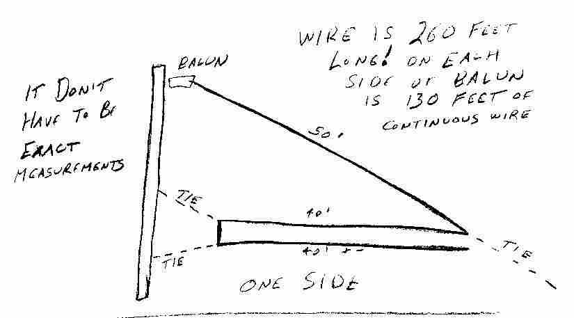
Simple Sketch showing path of antenna wire on one side of balun.
Quick Tips:
Here is how to install this antenna system and have it up and running in well under an hour, exluding push-pole installation of course.
- 1. Install the wires to your balun and connect the coax, hoist it into position and secure firmly.
- 2. Pull one wire out taught to your guy mount and secure temporarily.
- 3. Take the loose end of this same wire and secure it to the push-pole temporarily at the desired final installation height. Note: This end of the wire will be at the other end of the yard when finished.
- 4. Go back to the outbound end of the antenna, using a stepladder if necessary, pull the wire so that it is taught from the push-pole and lift the wire until it is perfectly horizontal.
- 5. With a magic marker or piece of tape, mark the sloping wire at the point where the wire from the push-pole crosses the sloping wire. This is where the outbound insulator is to be installed.
- 6. Install the outbound insulator and tie off (guy) this portion of the antenna to permanent tension.
- 7. Disconnect the loose end of the wire from the push-pole, pass it through an insulator and bring the loose end out to the outbound end and temporarily connect it to the now secure insulator outbound insulator, leaving 2 to 3 feet of loose pigtail extending through this insulator.
- 8. Pull the wires from the insulator toward the push-pole until they are in balance at equal lengths from the outbound end, at this bend take the insulator and give it a twist, release the loose pigtail at the outbound end, then secure the push-pole end of the top linear-loading wire and it's insulator to the push-pole at it's permanent position.
- 9. Install your first spacer (see spacers below) by passing the loose end of the wire through it, bring it up snug to the insulator, install the second insulator and give it a twist to hold it secure. Tie this insulator off to the push-pole as well, trying to keep the spacer vertical.
- 10. Install additional spacers, one about every five feet, to maintain separation of the upper and lower linear-loading sections.
- 11. When you reach the outbound end, install your last spacer at the insulator, form a loop in the lower wire for attaching a nylon tie off rope. Pull the rope to tighten the lower linear-loading wire and tie off to the guy mount. Wrap the remaining 2 or 3 feet of pigtail around the nylon rope.
- 12. Duplicate the above instructions for the other leg of the antenna!
SPACERS:
I take simple drinking straws to use for spacers. But reinforce them to two thicknesses for all the spacers except the inbound spacer near the push pole, this one is three or four thicknesses.
To strengthen a soda straw, you merely slit another soda straw end to end and insert it inside of the whole unslit soda straw.
You only need to pass the unslit whole soda straw over the wire for the inbound spacer, the other two or three slit straws can be added right over the wire and then slid into the whole unslit straw.
Joining the straws to the wires:
I take 24 inch long pieces of braided nylon, like mini-blind sash cord, fold it in half, hold it on one side of the top wire with the loop up and open, then I pass the loose ends of the rope over the wire and through the loop, pull it snug and let the ropes hang until I get all the ties (ropes) installed.
By taking a 12 inch long piece of 18 or 20 guage wire and bending a sharp turn at one end, you can use that to slip the ends of the ropes into and slide the soda straw over the wire pulling the rope down through the straw. Place the loose ends of the rope one on each side of the lower wire and tie a square knot, drawing the wire up tight against the soda straws. Don't worry if they are atilt right now, you can true them up later.
After the antenna is assembled, tied down nice and snug, and tuned. I will adjust the soda straws to vertical and place a dab of something like plasti-dip-your-grip or dumb gum over the tops of the straws to hide the nylon braid from UV and weather. I usually don't worry about the knot end or lower end of the straw.
Tune-Up:
If I have obstructions in the yard that interfere more with one leg than the other, I will make the shield side of the coax go to that side and the center conductor to the clearer of the legs. Ha; Now I tell you!
I normally tune both legs of the antenna first to 1.840 MHz, then I will continue to cut the clearer leg of the antenna all the way down to 1.950 MHz. I will then make a pigtail with an alligator clip on it and retune that leg of the antenna to 1.875 MHz. You can wrap the pigtail around the nylon guy and slide it down at least 6 inches away from the tuned pigtail end and it won't interfere with your upper band setting. In my case, I leave the pigtail connected as 1.875 MHz is one of my popular areas of the band for ragchewing. I may be over 50, but to really fit in up at 1.950, I need another 40 years under my belt, Hi Hi..... You may make other pigtails to center in other areas of the band also. It works on either leg of the antenna!
TTUL - 73+ de Gary - KGØZP
Questions or comments may be e-mailed directly from the home (index) page.
![]()